Denoising the Hama PDR20 DAB+/FM receiver
Posted · Last updated
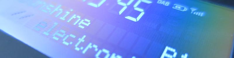
The Hama Digitalradio “PDR20” DAB+/FM fits right into a jacket pocket thanks to its 115x64mm form factor. I also need to admit that it appealed to me right away because of the stylized “floppy disk” icon (at least that’s my interpretation of the symbol) used to refer to memory locations beyond the four stations directly accessible. My main problem with this gadget was an annoying noise frequency (at around 1kHz) present on both audio signal outputs. So I decided to check if something could be done about that.
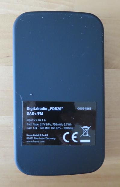
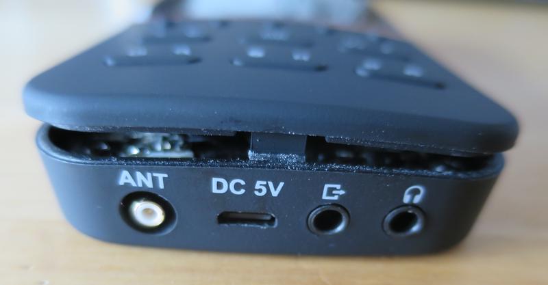
Besides a micro USB port to power the unit (and charge the internal battery), the device features a male SMB connector for the antenna (to be mated to the included 91cm long wire “dipole antenna”) and two audio output ports (line out, headphones out). Luckily, the case is only held together by a bunch of plastic clips (three each on the sides, one each on top and bottom) that don’t seem to break off easily. It could be opened without any damage. After my disastrous experience with a Caliber Audio DAB tuner, this came as a pleasant surprise.
What’s inside?
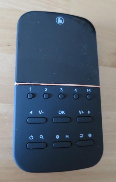
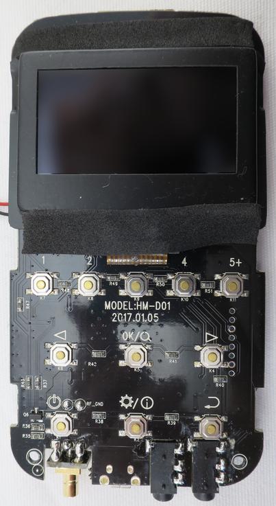
The PCB shows that the device is built around the Frontier Silicon FS2415 module (also going by the name of “Siena” on some forums). It is connected to the display via an I2C bus and uses an analog keyboard interface (resistors of values between 6.8k and 24k are located next to each of the pushbuttons).
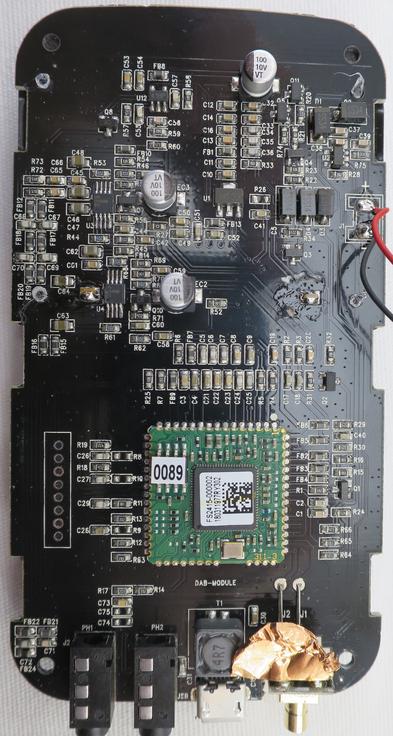
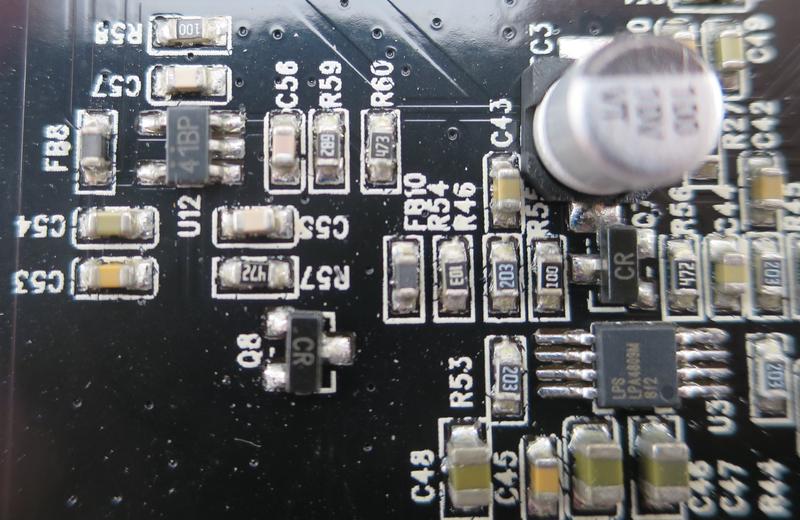
The reverse side is well compartmentalized:
- On the top right, there’s the charging circuit for the lithium polymer battery (attached using the wires to the right). Interestingly, it’s built entirely from discrete parts (a Shouding K13V MOSFET, some 1N5819 and 1N5822 diodes, and two CM7P61N-57-T voltage detectors). This probably also explains why more than three hours are required for a full charge. And the 3.3V LDO to the left of the charging circuit probably explains the short battery lifetime.
- The PWM circuit to control the brightness of the display backlight is located on the top left.
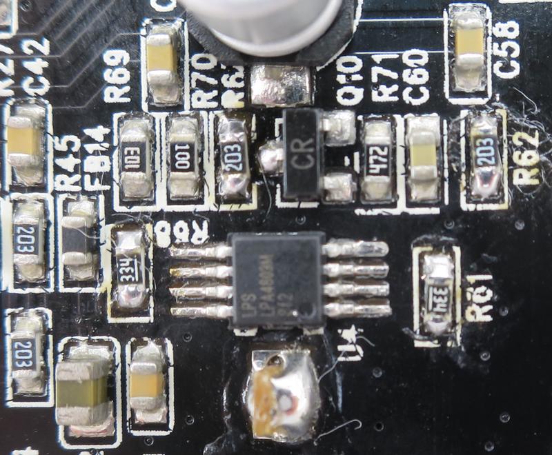
- Right below it, there are two largely identical amplifier circuits (built around the LPA4809M stereo amplifier IC). The one that drives the headphone output is followed by a passive filtering network, whereas the line-out only has a decoupling capacitor and a ferrite bead in the path to its 3.5mm connector.
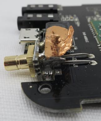
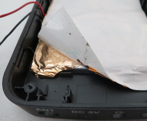
Have you wondered what the copper-colored thing on top of the antenna jack is? I noticed a little resistance when pulling the PCB from the case. Turns out the SMB antenna port has been soldered onto a tiny PCB itself, and two of its ground pins were soldered to some sticky copper foil that was attached to the back of the case (covering the battery and the rest of the case). The antenna jack is hooked up to the actual mainboard by means of two wire jumpers (labeled J1 and J2). Probably the board was originally designed for a different connector; this construction seems rather difficult to assemble, and not strictly 50 Ohms impedance either.
Where does the noise come from?
Back to my problem: There’s a very audible tone in the audio output, which I guesstimated to be at a frequency of around 1kHz. Virtually all components on the PCB are analog – except the backlight PWM in the top-left corner of the PCB.
I hooked up my scope to input of the PWM driver, and here’s some traces for its high, medium, and low brightness setting (horizontal: 1ms/div):
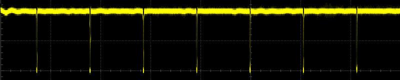

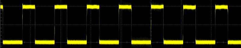
At a frequency of 937Hz, the PWM control signal sits right at my estimated frequency. The PWM signal toggles in each cycle, even when the display brightness is set to its maximum value, and as such the tone is audible across all backlight settings. Given the poor battery lifetime of the device even when backlight is turned low, it’s most likely I will only operate it on USB power, and was willing to sacrifice the possibilty to dim the display.
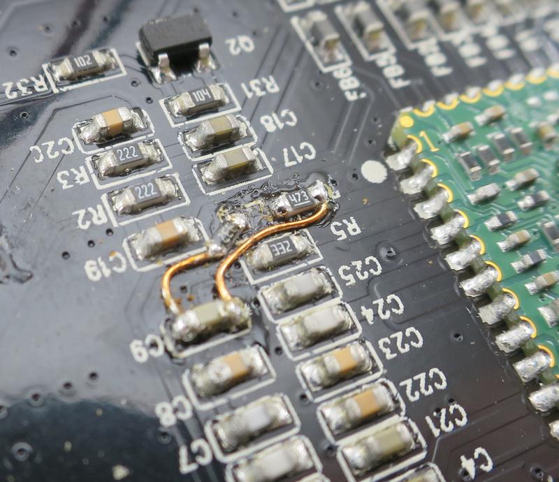
The driving pin from the FS2415 module was terminated to ground with a 47k resistor, and the PWM driver’s input held at a constant 3.3V using the existing 3.3k resistor (R4). Both power rails are conveniently available at the pins of nearby capacitor C9, thus the fix was easily done.
It’s not like there was no other space on the PCB to fit the PWM circuit, so why place it right next to the audio amplifiers? That’s like running an open sewage pipe right through your living room. Well, at least that unwanted signal is now gone from the audio output.
While we’re at it: Getting the line-out volume fixed
The volume control is realized in software, and both audio amplifiers are provided with the same (attenuated) signal at their inputs. As such, the signal level on the line-out pin follows the volume setting of the device, rather than staying at a constant level. This wouldn’t be as bad if the device would memorize the volume setting before being turned off, yet after startup the volume is always four ticks below its maximum. Raising it not only requires four button clicks, though, but frequently (not always) also a confirmation of the warning about the dangers of “unsafe volume”.
A brief look at the LPA4809M amplifier datasheet reveals how the amplification is determined: It’s the quotient of the feedback resistor and the input resistor values. By default, both are 20k resistors, so the overall gain is 1. Increasing the feedback resistor value (R61 and R68) to 330k (i.e., by a factor of about 16) nicely brought the output level on the line-out to a reasonable volume.
One last significant (but sporadic) issue
Unfortunately, sometimes the device randomly turns off when running off the built-in battery, regardless of the level of battery charge. Given the time it takes before it switches off (on the order of tens of minutes), I was unable to reproduce this repeatedly. Some initial investigation into the matter showed that the battery voltage is sampled using a 470k/120k voltage divider with 1uF stabilizing cap on the divided signal (R29, R30, C40). My guess is that noise couples into this signal, triggering the undervoltage protection and effectively shutting the device down. Increasing the value of C40 to 6.8uF seemed to improve things so far.